Posts

4. VIDEO PRESENTATION

Image
 PROJECT PRESENTION  You are required to produce a final presentation video with the MAX duration of 7 minutes. The video must explain the following components: • Explanation on how the data travels from Student’s PC to Ulearn System Server. Be creative and precise to get better marks. • Elaborate the findings and the experience that your team had discovered while conducting this project. This is our video presentation 🎥 :  Video 1: Presentation Video 

3. TCP/IP CONFIGURATION

Image
 TCP/IP CONFIGURATION  In this section, you are assumed have correctly identified the IP address for the Ulearn System Server. Therefore, you must produce a manual on how to configure the IP address on the server. You can use any operating system to demonstrate this task. The explanation should be supported with the screenshot and appropriate explanation. Manual : How to configure the IP address on the server 💻 The operating system that we will set as an example is Windows 10 Professional  Click windows button, and search for Control Panel . Click Open                2. Control Panel window is open. Select Network and Internet    3. Select Network and Sharing Center  4. Network and Sharing Center window is open. On the left panel, click Change adapter settings  5. Network Connections window is open. Every network adapter that have been installed on the computer including virtual network adapter or physical...

2. SUBNETTING CALCULATION

Image
   Subnetting Calculation       In this section, you are expecting to show the calculation on how to identify the IP address that was assigned for the Ulearn System Server based on the information given in the project scenario. Explain the concept and show the calculation to identify the IP address. Based on  🔗  project scenario  given, we will use subnet Class B.  Figure 1: Class B subnet list  Default Class B mask  = 255.255.0.0 (16 bits)  There will be 9 subnet = 8 faculties + 1 IT Center  IP Address = 172.16.0000 0000.0000 0000/16 As shown in Figure 1 above, the nearest network bits that we can use /20 because the number of subnets is 16 or we can follow step below.  Subnetting step: 1) Calculate required host bit to be borrowed by using this formula   2ⁿ >=  no. of subnets needed for this scenario, the calculation will be:  2ⁿ ≥ 9  2⁴ ≥ 9  no. of hos...

1. OSI LAYER MODEL

Image
The OSI Model  (Open Systems Interconnection Model)       The OSI model (Open System Interconnection Model)  is a conceptual framework that used to describe seven layers that computer systems use to communicate over a network. It was the first standard model for network communications, adopted by all major computer and telecommunication companies in the early 1980s.  The OSI was published in 1984 by the International Organization for Standardization (ISO).     The OSI model characterizes computing functions into a universal set of rules and requirements in order to support interoperability between different products and software. In the OSI reference model, the communications between a computing system are split into seven different abstraction layers as shown picture above: Physical, Data Link, Network, Transport, Session, Presentation, and Application. Though it does not always map directly to specific systems, the OSI Model ...

Project Scenario

Image
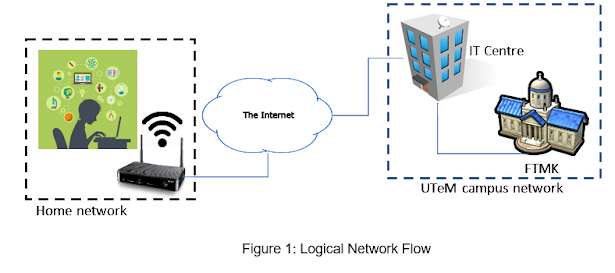
Group members:  1. NUR NADZIRAH BINTI MOHD ANUAR (B032110069) 2. AMIRAH BINTI AMRAN (B032110045) 3. ATHIRAH BINTI AHMAD NIZAM (B032110432) 4. FATIN MAISARAH BINTI KAMAROLZAMAN (B032110464)       The scenario of this project can be referred to Figure 1. Figure 1 shows the logical network flow from a home network to UTeM facilities. In this figure, a UTeM’s student is trying to access the Ulearn system located in the UTeM network facilities. The student is using her modem to connect to the public network before able to connect to the UTeM facilities. From the UTeM network, the data then was forwarded to IT Center where the Ulearn System server is located.      Students are required to suggest private addressing scheme used in UTeM network. Explain how you calculate the subnetting using FLSM based on the number of the faculties. The number of students of each faculty is within 500 – 1000 students. Each faculty is given their network address. Assign IT Ce...